Computer Networks Ethernet
How is Ethernet used in modern networks? What are Media Access Control addresses and how are they used in networking?

Disclaimer
This content is provided for educational and informational purposes only. The techniques and tools discussed, are intended to raise awareness about security risks and help developers and system administrators protect their systems.
We do not encourage, support, or condone any form of unauthorized access, exploitation, or malicious activity. All demonstrations were conducted in controlled environments with proper authorization.
Use this knowledge responsibly and always adhere to your local laws and ethical guidelines. Hacking should only be performed in environments where you have explicit permission.
The author assumes no responsibility for any damages or legal consequences arising from the misuse of this content. Always ensure you have proper authorization before testing or auditing any system!
Ethernet Basics
Ethernet is a contention-based access method that allows all hosts on a network to share the same bandwidth. Ethernet is widely used due to its scalability, which means you’ll be able to integrate new technologies like Fast Ethernet into your existing network infrastructure with relative ease. It’s also relatively easy to implement, and relatively easy to troubleshoot.
CSMA/CD
Ethernet networks use Carrier Sense Multiple Access with Collision Detection (CSMA/CD), a media access control contention method that allows devices to share bandwidth equally without two devices transmitting on the network medium at the same time.
To solve the problem of collisions that occur when packets are transmitted simultaneously by different hosts, CSMA/CD was created. And believe me, good collision management is critical. When one host sends a packet on a CSMA/CD network, all other hosts on the network receive and validate that packet.
The only effective way to prevent a transmission from propagating throughout the network is through bridges, switches, and routers!
How does the CSMA/CD protocol work? Take a look at the image below, where a collision has occurred in the network.

A host first checks for a digital signal on the line when it wants to transmit over the network. The host then proceeds with its transmission if all is clear, meaning no other host is transmitting. But that’s not all. To make sure that no other hosts are starting to transmit, the transmitting host constantly monitors the wire.
When the host detects another signal on the wire, it sends an extended jam signal. This causes all hosts on the segment to stop sending data (think of it as a busy signal). The hosts wait a while before attempting to transmit again in response to this jam signal. Back-off algorithms, represented by the clocks counting down on either side of the jammed devices, determine when the colliding stations will be able to transmit again. The hosts attempting to transmit will time out if collisions continue after 15 attempts.
Broadband/Baseband
Broadband and baseband are two ways to send analog and digital signals over a wire.
We hear a lot about broadband nowadays, because that’s pretty much what everyone is using at home. We can get both our analog voice and our digital data over the same network cable or physical medium. Broadband allows us to send both analog and digital signals by sending multiple frequencies of different signals over the same wire at the same time (frequency division multiplexing).
All LANs use baseband. This is where one signal uses all the bandwidth of the physical media. Ethernet, for example, uses all the available bandwidth because it only uses one digital signal at a time. If multiple signals from different hosts are sent at the same time, we get collisions. Wireless is the same, except that it uses only analog signaling over radio waves.
Bit Rates vs. Baud Rate
Bit rate refers to the number of bits of data (0’s and 1’s) transferred per second of digital or analog data. A value of 56,000 Bits Per Second (bps) means that 56,000 0s or 1s can be transmitted in one second. We simply refer to this as bps.
In the 1970s and 1980s, the term baud rate was in common use, but it was replaced by bps because it was more accurate. Baud was a metric named after a French engineer, Jean-Maurice-Émile Baudot. He used it to measure the speed of telegraph transmissions.
A baud is one electronic change of state per second, such as from 0.2 volt to 3 volt or from binary 0 to 1. Because a single change of state can involve more than a single bit of data, it’s been superseded by bps as a more precise definition of how much data you send or receive.
Wavelength
Electromagnetic radiation-radio wave, light wave, or even infrared (heat) wave creates characteristic patterns when it travels across space. Some of the patterns may be the same, and some of the patterns may be different.

Each wave is shaped and lengthened in a certain way. The wavelength is the distance between the peaks. If two wave patterns are different, we say they’re not on the same wavelength, and that’s how we distinguish different types of electromagnetic energy. In electronics, you could send traffic on different wavelengths simultaneously.
Half vs Full-Duplex
The original 802.3 Ethernet specification defines half-duplex Ethernet. Basically, when you’re running half-duplex, you’re using only one pair of wires. A digital signal is either being sent or received.
This is really not that different from full-duplex because you can both send and receive, you just can’t do it at the same time with half-duplex.
Here’s how it works: When a host receives a digital signal, it uses the CSMA/CD protocol to prevent collisions and to allow retransmission if a collision occurs.
Typical 10BaseT half-duplex Ethernet is only about 30 to 40% efficient because a large 10BaseT network will usually only provide 3 Mbps to 4 Mbps at most. It’s true that 100 Mbps Ethernet can and sometimes does run half-duplex. However, it’s not very common anymore.
Instead of using one measly pair of wires like half-duplex, full-duplex Ethernet uses two pairs of wires simultaneously. Full-duplex also uses a point-to-point connection between the sending device’s transmitter and the receiving device’s receiver (usually the switch). This means that you not only have faster data transfer, but also collision avoidance.
Now it’s like a multilane highway instead of the single lane of half-duplex, so you don’t have to worry about collisions. Full-duplex Ethernet is supposed to provide 100% efficiency in both directions; for example, you can get 20Mbps with full-duplex 10Mbps Ethernet, 200Mbps with Fast Ethernet, or even 2000Mbps with Gigabit Ethernet. But this rate is what is known as an aggregate rate. It means “you should get” 100% efficiency.
Ethernet at the Data Link Layer
Ethernet at the data link layer is responsible for Ethernet addressing. This is commonly referred to as hardware addressing or MAC addressing. Ethernet also frames packets received from the network layer and prepares them to be transmitted on the local network.
Hexadecimal addresses are used for Ethernet MAC addresses. So let’s talk about binary, decimal, and hexadecimal addresses and how to convert one to the other before we talk about MAC addresses.
Binary to Decimal and Hexadecimal Conversion
Before we discuss the TCP/IP protocol stack and IP addressing, it is important to understand the differences between binary, decimal, and hexadecimal numbers and how to convert one format to another.
Let’s begin with binary numbers. It’s really quite simple. Each digit is called a bit (short for binary digit), and each digit is limited to being either a 1 (one) or a 0 (zero). Usually we count either 4 or 8 bits together, which are called nibbles and bytes, respectively.
The interesting thing about binary numbering is that the value is represented in a decimal format. The typical decimal format is the base-10 numbering scheme that we’ve all used since kindergarten. The binary numbers are placed in a range of values, starting on the right and moving to the left. Each position has twice the value of the previous position.
Just to remind you:
| Nibble Values | Byte Values |
|---|---|
| 8 4 2 1 | 128 64 32 16 8 4 2 1 |
Bit:   1   1   1   1
       |   |   |   |
Val:   8   4   2   1

Bit:   1   1   1   1   1   1   1   1
       |   |   |   |   |   |   |   |
Val: 128  64  32  16   8   4   2   1
So if you put a one (1) in a value location, the nibble or byte will take the decimal value and add it to any other value locations with a 1. And if you put a zero (0) in a bit location, you won’t count the value.
Let me explain, if we have a 1 in each place of our nibble, then we add 8 + 4 + 2 + 1 to get a maximum value of 15. Another example of nibbled values is 1010, which means that the 8-bit and 2-bit have been switched on and the decimal value is 10. If the binary nibble value is 0110, the decimal value is 6 because the 4 and 2 bits were enabled.
But bytevalues can be added together, which is well above 15. For example, the byte binary value looks like this (remember, 8 bits equal one byte) if we count each bit as one (1):
- 11111111
Since each bit spot is turned on, we then count each one up:
- 128 + 64 + 32 + 16 + 8 + 4 + 2 + 1 = 255
Many other decimal values can be equal to a binary number:
- 10010110
What are the bits that are on? The 128, 16, 4, and 2 bits are on, let’s sum those:
- 128 + 16 + 4 + 2 = 150
It is very important that you memorize the following table:
| Binary Value | Decimal Value |
|---|---|
| 10000000 | 128 |
| 11000000 | 192 |
| 11100000 | 224 |
| 11110000 | 240 |
| 11111000 | 248 |
| 11111100 | 252 |
| 11111110 | 254 |
| 11111111 | 255 |
Unlike binary or decimal, hexadecimal addressing is converted by reading nibbles, not bytes. By using a nibble, we can easily convert these bits to hex. The first thing to understand is that the hexadecimal address scheme only uses the numbers 0 through 9. The letters A, B, C, D, E, and F are used to represent 10, 11, 12, 13, 14, and 15, respectively, because the numbers 10, 11, 12, and so on cannot be used (because they are two-digit numbers).
| Hexadecimal Value | Binary Value | Decimal Value |
| 0 | 0000 | 0 |
| 1 | 0001 | 1 |
| 2 | 0010 | 2 |
| 3 | 0011 | 3 |
| 4 | 0100 | 4 |
| 5 | 0101 | 5 |
| 6 | 0110 | 6 |
| 7 | 0111 | 7 |
| 8 | 1000 | 8 |
| 9 | 1001 | 9 |
| A | 1010 | 10 |
| B | 1011 | 11 |
| C | 1100 | 12 |
| D | 1101 | 13 |
| E | 1110 | 14 |
| F | 1111 | 15 |
Notice how the first 10 hex numbers (0-9) are identical to the decimals…
Let us assume that you have something like this: 0x6A. (Some vendors put 0x in front of characters so you know it’s hex, others give you an h. It has no other special meaning). What are the binary value and the decimal value?
In order to answer this question correctly, all you have to remember is that each hexadecimal character is a nibble, and that two hexadecimal characters together make up a byte.
In order to find out the binary value, you first have to put the hex characters into two nibbles and then put them together to form a byte. 6 = 0110 and A (decimal 10) = 1010, so the complete byte is 01101010.
Just break the byte into nibbles to convert from binary to hex.
For example, suppose you have the binary number 01010101. First, decompose it into nibbles 0101 and 0101. The value of each nibble is 5 because the 1 and 4 bits are on. Hex response becomes 0x55. And speaking in decimal format, the resulting binary number is 01010101, which translates to 64 + 16 + 4 + 1 = 85.
Ethernet Addressing
Now that you’ve mastered how to convert binary-to-decimal and hexadecimal addresses, we can get started on how Ethernet addressing works. It makes use of the Media Access Control (MAC) address that is burned into each and every Ethernet Network Interface Card (NIC). The MAC, or hardware, address is a 48-bit (6-byte) address that’s written in hexadecimal format.

The Organizationally Unique Identifier (OUI) is assigned to an organization by the Institute of Electrical and Electronics Engineers (IEEE). It consists of 24 bits or 3 bytes.
In turn, the organization assigns a globally managed address (24 bits or 3 bytes). This address is unique to each adapter it manufactures.
Take a good look at the image above.
To indicate whether the destination MAC address is a unicast or multicast/broadcast Layer 2 address, the Individual/Group (I/G) address bit is used. It is an individual MAC address and is unicast if the bit is set to 0. It is a group address and a multicast/broadcast address if the bit is set to 1.
The Local/Global (L/G) bit is the next bit. This bit is used to determine if the MAC address is the Burned-In-Address (BIA) or a locally changed MAC address.
A locally managed or vendor-assigned code represents the lowest-order 24 bits of an Ethernet address. This part typically starts with 24 0s for the first card made. It continues in sequence until it has 24 1s for the last (16,777,216th) card made.
You’ll find that many manufacturers use the same 6 hexadecimal numbers for the last 6 characters of their serial numbers on the same card.
Ethernet Frames
Combining bits into bytes and bytes into frames is the responsibility of the data link layer. Framing is used at the data link layer to encapsulate packets passed from the network layer for transmission over some form of physical media access.
Ethernet stations pass data frames to one another using a set of bits called a MAC frame format. A Cyclic Redundancy Check (CRC) provides error detection. But keep in mind that this is error detection, not error correction!

-
Preamble: An alternating 1,0 pattern provides a clock at the beginning of each packet. This allows receiving devices to lock the incoming bit stream.
-
Start of Frame Delimiter (SOF)/Synch: The preamble is seven octets and the start of frame (SOF) is just one octet (synch). The SOF is 10101011, with the last pair of 1s allowing the receiver to get into the alternating 1,0 patterns anywhere in between and yet sync and detect the start of the data.
-
Destination Address (DA): The least significant bit (LSB) of a 48-bit value is transmitted first. The DA, which can be a single address or a broadcast or multicast MAC address, is used by receiving stations to determine whether an incoming packet is addressed to a specific host. Note that a multicast is sent only to a similar subset of hosts on a network, whereas a broadcast is all 1s (or Fs in hex) and is sent to all devices.
-
Source Address (SA): Using the LSB first, the SA is a 48-bit MAC address used to identify the transmitting device. Within the SA field, broadcast and multicast address formats are illegal.
-
Length or Type: 802.3 uses a length field, but the Ethernet frame uses a type field to identify the protocol at the network layer. By itself, 802.3 is not able to identify the upper layer protocol that is routed and must be used with a LAN protocol.
-
Data: These are packets transmitted from the Network Layer, down to the Data Link Layer. Size can vary between 64 and 1500 bytes.
-
Frame Check Sequence (FCS): The FCS is a field that is placed at the end of the frame and is used to store the CRC of the frame.
Let’s examine some frames. As you can see, there are only three fields in the following frame: Destination, Source, and Type, which shows up as Protocol Type:
Destination:  00:60:f5:00:1f:27
Source:    00:60:f5:00:1f:2c
Protocol Type: 08-00 IP
This is an Ethernet_II frame. Note that the Type field is IP, or 08-00 (usually simply called 0x800) in hex.
The next frame must also be an Ethernet_II frame because it has the same fields:
Destination:  ff:ff:ff:ff:ff:ff Ethernet Broadcast
Source:    02:07:01:22:de:a4
Protocol Type: 08-00 IP
Do you have any idea that this frame is a broadcast frame? You can tell because the destination hardware address is all binary 1s or hexadecimal Fs.
Let’s see another Ethernet_II frame. As you can see, this Ethernet frame is the same Ethernet_II frame that we are using with the IPv4 routed protocol. The difference is that the Type field is 0x86dd when we are carrying IPv6 data. When we are carrying IPv4 data, we use 0x0800 in the Protocol field:
Destination: IPv6-Neighbor-Discovery_00:01:00:03 (33:33:00:01:00:03)
Source: Aopen_3e:7f:dd (00:01:80:3e:7f:dd)
Type: IPv6 (0x86dd)
This is what is nice about Ethernet_II frames. Because of the Protocol field, we can run any protocol that is routed at the network layer, and it will carry the data because it can identify that particular network layer protocol!
Ethernet at the Physical Layer
The first implementation of Ethernet was done by a group called DIX (Digital, Intel, and Xerox). DIX created and implemented the first Ethernet LAN specification. The IEEE used this specification to create the IEEE 802.3 Committee. This was a 10 Mbps network. It ran on coax, then twisted pair, and finally fiber optic physical media.

The standards body that creates the physical layer specifications for Ethernet is the Electronic Industries Association and the newer Telecommunications Industry Alliance (EIA/TIA). The EIA/TIA specifies that Ethernet uses a Registered Jack, or RJ, connector over Unshielded Twisted Pair, or UTP, cable (RJ-45). However, in the industry, this is referred to simply as an 8-pin modular connector.
Each type of Ethernet cable specified by EIA/TIA has what is known as inherent attenuation. This is defined as the loss of signal strength as it travels along the length of the cable and is measured in decibels (dB). Categories are used to measure the cables used in business and residential markets. A higher quality cable will have a higher rated category and a lower level of attenuation. Category 5 is superior to Category 3 because Category 5 has more windings per foot, reducing cross-talk. Crosstalk is the unwanted interference of signals from adjacent pairs of wires in the cable.
Here are the original standards for IEEE 802.3:
-
10Base2: Also known as ThinNet. Can support up to 30 workstations on a single segment. The system uses 10Mbit/s baseband technology, coaxial cable up to 185m, and a physical and logical bus with Attachment Unit Interface (AUI) ports. The 10 stands for 10 Mbps, the base stands for baseband technology - a signaling method for communicating on the network - and the 2 stands for nearly 200 meters. To connect to a network, 10Base2 Ethernet cards use BNC (British Naval Connector, Bayonet Neill-Concelman, or Bayonet Nut Connector) and T connectors.
-
10Base5: Aka Thicket, 10Base 5 uses a physical and logical bus with AUI connectors, 10Mbps baseband technology, and coaxial cable up to 500m long. With repeaters and 1,024 users for all segments, you can go up to 2,500 meters.
In your career, you will never have to deal with 10Base2 or 10Base5. These technologies have been out of use for the last 20 years, but they are a reference point.
- 10BaseT: This is 10Mbps over Category 3 UTP cabling. Each device must connect to a hub or switch, and you can have only one host per segment or wire, unlike 10Base2 and 10Base5 networks. It uses an RJ-45 connector (an eight-pin modular connector) with a star topology on the physical side and a bus on the logical side.
Each of the 802.3 standards defines an AUI that allows a one-bit-at-a-time transition from the data link media access method to the physical layer. This allows the physical layer to support both existing and new technologies while keeping the MAC address constant. The original AUI interface was a 15-pin connector that allowed a transceiver to provide a 15-pin to twisted pair conversion.
There is one problem, though the AUI interface can’t support 100 Mbps Ethernet because of the high frequencies that are involved. So 100BaseT essentially needed a new port, and the 802.3u specifications provided one called Media Independent Interface (MII), which offers 100Mbps throughput. The MII uses a nibble. You remember that nibble is defined as 4 bits. Gigabit Ethernet transmits 8 bits at a time using a Gigabit Media Independent Interface (GMII).
802.3u (Fast Ethernet) is compatible with 802.3 Ethernet. This is because they share the exact same physical characteristics. Fast Ethernet and Ethernet preserve the frame format used by 10BaseT Ethernet, and they use the same Maximum Transmission Unit (MTU) and MAC mechanisms. In fact, Fast Ethernet is simply an extension of the IEEE 802.3 specification, and therefore offers us a 10 times speed increase over 10BaseT.
-
100BaseTX (IEEE 802.3u): Commonly known as Fast Ethernet, 100BaseTX uses EIA/TIA Category 5/5e or 6 and UTP two-pair cabling. It uses an RJ-45 connector with a physical star topology and a logical bus, allowing one user per segment up to 100 meters (328 feet) long.
-
100BaseFX (IEEE 802.3u): This is a point-to-point topology that uses 62.5/125-micron multimode fiber cabling up to 412 meters. It uses ST and SC connectors. These are media interface connectors.
-
1000BaseCX (IEEE 802.3z): This is a copper twisted pair called Twinax (a balanced coaxial pair) that can only run up to 25 meters (82 feet). It uses a special nine-pin connector called the High-Speed Serial Data Connector (HSSDC).
-
1000BaseT (IEEE 802.3ab): 1000BaseT is up to 100 meters (328 feet) long and uses Category 5, four-pair UTP cabling.
-
1000BaseTX: 1000BaseTX uses Category 5 and two-wire UTP cabling up to 100m in length. Category 6 cabling has replaced 1000BaseTX.
-
1000BaseSX (IEEE 802.3z): This implementation of Gigabit Ethernet runs over multimode fiber rather than twisted-pair copper cable. It uses a short-wavelength laser. Multimode fiber (MMF), which uses a 62.5- and 50-micron core, uses an 850 nanometer (nm) laser. The 62.5-micron fiber can extend up to 220 meters; the 50-micron fiber up to 550 meters.
-
1000BaseLX (IEEE 802.3z): This is a single mode fiber which uses a 9 micron core, 1,300nm laser and can go from 3km to 10km.
-
10GBaseT: Created by the IEEE 802.3an committee, 10GBaseT enables 10Gbps connections over traditional UTP (Category 5e, 6, 6A, or 7) cable. The conventional RJ-45 used for Ethernet LANs can be used for 10GBaseT. It is capable of supporting signal transmission over the full 100-meter (300 ft) distance specified for LAN cabling. This is the most economical way to implement a 10 Gbps link!
-
10GBaseSR: Uses short wavelength 850 nm lasers over multimode fiber for this implementation of 10 Gigabit Ethernet. Depending on the size and quality of the fiber, the maximum distance is between 2 and 300 meters (990 feet).
-
10GBaseLR: Uses 1,310 nm long-wavelength lasers over single-mode fiber for this implementation of 10 Gigabit Ethernet. Depending on the size and quality of the fiber, the maximum transmission distance ranges from 2 meters to 10 km or 6 miles.
-
10GBaseER: Uses extra-long wavelength lasers at 1,550 nm for this implementation of 10 Gigabit Ethernet over single-mode fiber. It has the largest possible transmission distances of all 10 Gigabit technologies: anything from 2 meters to 40 km, which again depends on the size and the quality of the used fiber.
-
10GBaseSW: 10GBaseSW, as described in IEEE 802.3ae, is a variant of 10GBaseS for MMF with an 850 nm laser transceiver and a bandwidth of 10 Gbps. Cable lengths of up to 300 meters can be supported. This type of media is designed to be connected to a SONET device.
-
10GBaseLW: 10GBaseLW is a mode of 10GBaseL that supports a link length of 10 km on standard singlemode fibers (SMF) (G.652). This type of media is also intended for connection to SONET equipment.
-
10GBaseEW: 10GBaseEW is a mode of 10GBase E supporting up to 40km link length on SMF based on G.652 using 1550nm optical wavelength. This is another media type designed to connect to SONET equipment.
-
40GBaseT: An IEEE 802.3bq committee standard, 40GBaseT supports Ethernet speeds up to 40Gbps and is also used for 25Gbps Ethernet connections commonly found in server NICs. 40GBaseT is limited to 30 meters, a shorter distance than slower Ethernet types. For data center cabling, this is typically sufficient. To support the high data rates of 25GBaseT and 40GBaseT, Category 8 cabling is required.
The following table provides a good summary:
| Ethernet Name | Cable Type | Maximum Speed | Maximum Transmission Distance | Notes |
|---|---|---|---|---|
| 10BaseT | UTP | 10 Mbps | 100 meters per segment | One of the most popular network cabling schemes. |
| 100BaseTX | UTP, STP | 100 Mbps | 100 meters per segment | Two pairs of Category 5 UTP. |
| 10BaseFL | Fiber | 10 Mbps | Varies (ranges from 500 meters to 2,000 meters) | Ethernet over fiber optics to the desktop. |
| 100BaseFX | MMF | 100 Mbps | 2,000 meters | 100 Mbps Ethernet over fiber optics. |
| 1000BaseT | UTP | 1000 Mbps | 100 meters | Four pairs of Category 5 or higher. |
| 1000BaseTX | UTP | 1000 Mbps | 100 meters | Two pairs of Category 6 or higher. |
| 1000BaseSX | MMF | 1000 Mbps | 550 meters | Uses SC fiber connectors. Max length depends on fiber size. |
| 1000BaseCX | Balanced, shielded copper | 1000 Mbps | 25 meters | Uses a special connector, the HSSDC. |
| 1000BaseLX | MMF and SMF | 1000 Mbps | 550 meters | multimode/2,000 meters single mode Uses longer wavelength laser than 1000BaseSX. Uses SC and LC connectors. |
| 10GBaseT | UTP | 10 Gbps | 100 meters | Connects to the network like a Fast Ethernet link using UTP. |
| 10GBaseSR | MMF | 10 Gbps | 300 meters | 850 nm laser. Max length depends on fiber size and quality. |
| 10GBaseLR | SMF | 10 Gbps | 10 kilometers | 1,310 nm laser. Max length depends on fiber size and quality. |
| 10GBaseER | SMF | 10 Gbps | 40 kilometers | 1,550 nm laser. Max length depends on fiber size and quality. |
| 10GBaseSW | MMF | 10 Gbps | 400 meters | 850 nm laser transceiver. |
| 10GBaseLW | SMF | 10 Gbps | 10 kilometers | Typically used with SONET. |
| 10GBaseEW | SMF | 10 Gbps | 40 kilometers | 1,550 nm optical wavelength. |
| 40GBaseT | UTP Category 8 | 40 Gbps | 30 Meters | Connects to the network like a Fast Ethernet link using UTP. |
Ethernet over Other Standards
IEEE 1905.1-2013 is an IEEE standard defining a converged wireless and wired digital home network.
Technologies covered will include IEEE 802.11 (Wi-Fi), IEEE 1901 (HomePlug, HD-PLC) powerline networking, IEEE 802.3 Ethernet, and Multimedia over Coax (MoCA). 1905.1-2013 was released in April 2013.
The IEEE Power Line Communication Standards Committee (PLCSC) sponsors the IEEE 1905.1 Standard Working Group.
Ethernet over Power Line
IEEE 1901, also known as Power Line Communication (PLC) or Power Line Digital Subscriber Line (PDSL), was published in February 2011 as a standard for Broadband over Power Line (BPL).

This technology has been theoretically available for decades, but the lack of IEEE standards has prevented its adoption.
Recently, this technology has been gaining traction, especially with utility companies. It collects data from the electricity meter installed in your home. This information is then passed on to the power company, and there is a specific report on how much electricity is being used in your home.
Home Internet access can also be provided using this technology. For a computer (or other appliance), just plug a BPL modem into any electrical outlet in a home and get high-speed Internet access.

Any electrical outlet can be used with the BPL modem to receive the ISP connection to the Internet after the gateway is connected through the coupler to the meter bank for the building.
There are still the following challenges to overcome:
-
The fact that power lines tend to be noisy.
-
The frequency at which the information is transmitted is used by the short wave, and the unshielded power lines can act as antennas and thus interfere with the short wave communications.
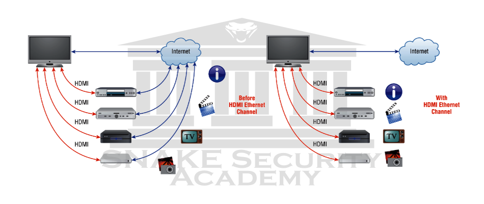
Ethernet over HDMI
Combining the signal quality of HDMI connectivity with the power and flexibility of home entertainment networking, HDMI Ethernet Channel technology combines video, audio and data streams in a single HDMI cable.