Computer Networks OSI Model
Introduction to OSI Model applications and its necessity...

Disclaimer
This content is provided for educational and informational purposes only. The techniques and tools discussed, are intended to raise awareness about security risks and help developers and system administrators protect their systems.
We do not encourage, support, or condone any form of unauthorized access, exploitation, or malicious activity. All demonstrations were conducted in controlled environments with proper authorization.
Use this knowledge responsibly and always adhere to your local laws and ethical guidelines. Hacking should only be performed in environments where you have explicit permission.
The author assumes no responsibility for any damages or legal consequences arising from the misuse of this content. Always ensure you have proper authorization before testing or auditing any system!
OSI Model
The Open Systems Interconnection (OSI) is a reference model for building layered networks. Designed to enable different networks to communicate reliably between disparate systems, the OSI model has seven hierarchical layers.
- The Layered Approach : Essentially, a reference model is a conceptual blueprint of how communication will occur. It takes into account all of the processes that need to be in place in order for communication to be effective, and organizes these processes into logical groupings called layers. These are called layered architectures.
It’s worth pointing out that these same advantages are true for any layer model, including TCP/IP. You should understand that the central purpose of the OSI model, and of all network models, is to allow networks from different vendors to work together smoothly.
We’ll talk about TCP/IP later on
Remember, the OSI is not a physical model it’s a conceptual, comprehensive, but fluid guideline that application developers use to design and implement applications that run on a network. This includes the creation and implementation of network standards, equipment, and internetwork systems.
The OSI model layers are:

The first three layers define the rules for how host applications communicate with each other and with end users.

The bottom four layers define how the actual data will be transferred from end-to-end.

Layer 1: Physical layer
The physical layer handles sending and receiving unstructured raw data between a device like a NIC, Ethernet Hub, or Network Switch, and a physical data media.
It converts the digital bits into electrical, radio, or optical signals.
The Bluetooth, Ethernet, and USB standards are examples of the physical layer. The CAN standard is an example of a lesser known physical layer specification.
The physical layer also specifies how to encode a physical signal, such as an electrical voltage or a pulse of light. For example, a 1 bit can be represented on a copper wire by the transition from a 0 volt to a 5 volt signal, while a 0 bit can be represented by the transition from a 5 volt to a 0 volt signal. As a result, common physical layer problems are often related to improper media termination, EMI or noise scrambling, and misconfigured or malfunctioning NICs and hubs.
Layer 2: Data link layer
The data link layer provides the physical transmission of data and handles error reporting, network topology, and flow control. This means that the data link layer ensures that messages are delivered to the correct device on a LAN using hardware (MAC) addresses, and translates messages from the network layer into bits for the physical layer to transmit.

The data link layer formats the message into pieces, each of which is called a data frame, and adds a custom header that contains the hardware addresses of the destination and the source.
The data link layer uses hardware addressing, specifically MAC addresses, to allow a host to send packets to individual hosts on a local network and to send packets between routers.
At the data link layer, each time a packet is sent between routers, it is framed with control information. At the receiving router, this information will be removed, leaving only the original packet in its entirety.
The packet continues to be framed for each hop until the packet is finally delivered to the correct recipient host. What’s important to understand is that the packet is never modified along the way, but is simply wrapped with the type of control information needed to correctly deliver the packet to the different types of media.
If you look at it, you will see that the IEEE 802.2 standard is not only used in conjunction with the other IEEE standards, but it also adds functionality to those standards.
The data link layer of the IEEE Ethernet consists of two sub-layers:
-
Media Access Control (MAC) : This determines how the packets will be placed on the media. Contended media access is “First Come, First Served” access where everyone shares the same bandwidth. Like logical topologies, physical addressing is defined here. So, what’s a logical topology? It’s the path of signalling through a physical topology. At this sublayer, you can also use line discipline, error reporting (not correction), ordered delivery of frames, and optional flow control.
-
Logical Link Control (LLC) : An LLC header is responsible for identifying and then encapsulating network layer protocols. It tells the data link layer what to do with a packet when it receives a frame. Here is how it works: A host receives a frame and looks at the LLC header to determine the packet’s destination, such as the network layer IP protocol. Flow control and control bit ordering can also be provided by the LLC.
The result of the IEEE 802 subcommittees and their work on standards for local and metropolitan area networks (LANs/MANs) is one of the major components of the data link layer. The committee met in February 1980, and the name Project 802 was created using the 80 from 1980 and the 2 from the second month. The name of any 802 standard always includes a dot (.) followed by either a single or double number. The numbers indicate specific categories within 802 standard.
| Standard | Topic |
|---|---|
| 802.1 | LAN/MAN Management (and Media Access Control Bridges) |
| 802.2 | Logical Link Control |
| 802.3 | CSMA/CD (Ethernet) |
| 802.4 | Token Passing Bus |
| 802.5 | Token Passing Ring |
| 802.6 | Distributed Queue Dual Bus (DQDB) Metropolitan Area Network (MAN) |
| 802.7 | Broadband Local Area Networks |
| 802.8 | Fiber-Optic LANs and MANs |
| 802.9 | Isochronous LANs |
| 802.10 | LAN/MAN Security |
| 802.11 | Wireless LAN |
| 802.12 | Demand Priority Access Method |
| 802.15 | Wireless Personal Area Network |
| 802.16 | Wireless Metropolitan Area Network (also called WiMAX) |
| 802.17 | Resilient Packet Ring |
Please note that 802.1, 802.3, 802.11, and 802.15 are the only 802 standards that are active. The other standards are either inactive or in hibernation.
Layer 3: Network Layer
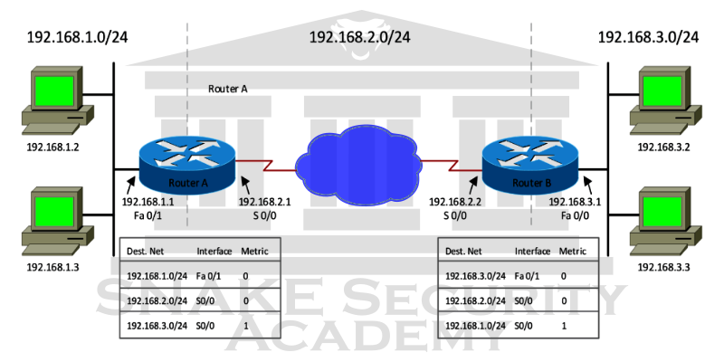
The network layer manages the logical addressing of devices, tracks the location of devices on the network, and determines the best method for moving data. Traffic between devices that are not locally connected must be transported at the network layer. Routers are Layer 3 devices defined at the network layer that provide routing services within a network.
Whenever packets arrive at the router interface, the router checks the destination IP address. The router looks up the destination network address in the routing table if the packet is not destined for that particular router. Once the router has selected an exit interface, the packet is sent to that interface for framing and transmission to the local network. The router drops the packet if it can’t find an entry in the routing table for the packet’s destination network.
At the network layer, two types of packets are used:
-
Data Packets : They transport user data across the Internetwork. Protocols that are in place to support data traffic are called router protocols. Two examples of routed protocols are the Internet Protocol (IP) and the Internet Protocol version 6 (IPv6)
-
Route-Update Packets : used to update nearby routers about the networks connected to all routers within the Internetwork. The protocols that send route update packets are called routing protocols, and some of the more common ones are the Routing Information Protocol (RIP), RIPv2, the Enhanced Interior Gateway Routing Protocol (EIGRP), and the Open Shortest Path First (OSPF). Route update packets are used to assist in the creation and maintenance of routing tables on each router.
-
Network Addresses : This is a protocol-dependent network address. Because each routing protocol tracks a network that includes different addressing schemes, such as IP and IPv6, a router must maintain a routing table for each routing protocol.
-
Interface : This is the exit interface a packet takes if it is intended for a specific network.
-
Metric : This value represents the distance to the remote network. This distance is calculated differently for different routing protocols. Some routing protocols, most notably RIP, use a hop count - the number of routers that a packet will pass through on its way to a remote network. Other routing protocols alternatively use bandwidth, line delay, and even something called a tick count, which is 1/18 of a second, to make routing decisions.
Routers break up broadcast domains, which means that by default, broadcasts don’t pass through a router. This is a good thing because it reduces network traffic. Routers also break up collision domains. However, this can also be done with Layer 2 (data link layer) switches.
Here are a few things to keep in mind about routers:
- By default, routers don’t forward broadcast or multicast packets.
- Routers determine the next-hop router to forward the packet to by the logical address in a network layer header.
- Routers can use administrator-created access lists to control security for the types of packets allowed to enter or leave an interface.
- Routers can provide Layer 2 bridging if needed. They can also route through the same interface simultaneously.
- Connections between virtual LANs (VLANs) are provided by Layer 3 devices (in this case, routers).
- Routers can provide Quality of Service (QoS) for certain types of network traffic.
Layer 4: Transport Layer
The transport layer is responsible for segmenting data, then reassembling it to form a data flow. The services that reside in the transport layer take the data from the applications in the upper layer and reassemble it into the same data stream. It provides end-to-end data transport services and is capable of establishing a logical connection between sending and receiving hosts on the network.
The transport layer provides the mechanisms for the multiplexing of upper layer applications, the establishment of virtual connections, and the termination of virtual circuits. It also hides the many and varied details of all network-related information from the higher layers, making data easier to transmit.
We will talk about TCP and UDP later
Layer 5: Session Layer
The Session layer handles the establishment, management, and termination of sessions between entities in the Presenter layer. Dialog control between devices or nodes is also provided by this layer. It coordinates communication between systems and serves to organize their communication by offering three different modes: one direction (simplex); both directions, but only one direction at a time (half duplex); and bi-directional (full duplex). To summarize: The session layer basically keeps the data of one application separate from the data of other applications. The ability to have multiple Web browser sessions on your desktop at the same time is a good example of the Session Layer.
Layer 6: Presentation Layer
The presentation layer gets its name from its purpose: it presents data to the application layer and is responsible for data translation and code formatting.
Conversion of data to a standard format before transmission is a successful data transfer technique. Computers are configured to receive this generically formatted data and then convert it to its native format for reading for example, from EBCDIC to ASCII, or from Unicode to ASCII, to name a few. By providing translation services, the presentation layer ensures that the data transmitted by the application layer of one system can be read and understood by the application layer of another system.
Tasks like compressing, decompressing, encrypting, and decrypting are all associated with this layer. Even multimedia operations involve some presentation layer standards.
Layer 7: Application Layer
The point at which users actually communicate or interact with the computer is the application layer of the OSI model. Technically, users communicate with the network stack through application processes, interfaces, or application programming interfaces (APIs). These interfaces connect the application being used to the computer’s operating system.
Encapsulation
Data goes through encapsulation when a host sends data over a network to another device: At each layer of the OSI model, it’s wrapped in protocol information. Each layer only communicates with its peer layer on the receiving equipment.

Each layer uses Protocol Data Units (PDUs) to communicate and exchange information. PDUs are the storage location for the control information associated with the data in each layer of the model. They are usually attached to the header at the beginning of the data field, but they can also be attached to the trailer, or the end of the data field.
This is how the data encapsulation method works:
- The user’s information is converted into data for transmission over the network.
- A reliable connection between the sending and receiving hosts is established by converting the data into segments.
- The segments are converted into packets, or datagrams, and a logical address is placed in the header so that each packet can be routed through an Internet network. A packet carries one segment of data on it.
- For transmission on the local network, packets or datagrams are converted into frames. To uniquely identify hosts on a local network segment, hardware (Ethernet) addresses are used. Frames are used to carry packets.
- A digital encoding and clocking scheme is used to convert frames to bits.