Computer Networks Wiring
Introduction to Networking Connectors and Wiring Standards...

Disclaimer
This content is provided for educational and informational purposes only. The techniques and tools discussed, are intended to raise awareness about security risks and help developers and system administrators protect their systems.
We do not encourage, support, or condone any form of unauthorized access, exploitation, or malicious activity. All demonstrations were conducted in controlled environments with proper authorization.
Use this knowledge responsibly and always adhere to your local laws and ethical guidelines. Hacking should only be performed in environments where you have explicit permission.
The author assumes no responsibility for any damages or legal consequences arising from the misuse of this content. Always ensure you have proper authorization before testing or auditing any system!
Physical Media
Even though most of what we use in our homes and even on the street today are wireless networks, these networks still rely on physical connections somewhere, be it in the backbone, tower connection, and/or data centers.
The most common types of physical connections in today’s networks are:
- Twisted-pair
- Fiber optic
Twisted-Pair Cable
A twisted-pair cable is made up of a number of individually insulated wires that are twisted together in pairs. It is sometimes called shielded twisted-pair (STP) because a metallic shield is placed around it. Cable without an outer shield is used in twisted-pair Ethernet networks (10BaseT, 100BaseTX, 1000BaseTX, 10GBaseT, and 40GBaseT) and is called unshielded twisted-pair (UTP).
Twinaxial Cable
For short distance, high speed connections such as 10 and 40G Ethernet connections in a data center, Twinaxial cabling is used. Twinaxial cabling is also known as Twinax cabling. The advantage of using twinaxial cabling is that there is a significant cost savings compared to fiber optic cabling, as twinaxial cabling is based on copper. Using these cables can be a significant cost savings if your distance is 10 meters or less.
Ethernet Cables
A code that follows this format is used to describe Ethernet cable types: N <Signaling> X.
- N : refers to the signaling rate in megabits per second.
- <Signaling> : represents the type of signaling either baseband or broadband
- X : is a unique identifier for a particular Ethernet cabling scheme
Example: 100BaseX. The 100 tells us that the transmission speed is 100 Mb, or 100 megabits. The value of the X can mean a number of different things; for example, a T is short for twisted pair. This is the standard for running 100 megabit Ethernet over two pairs (four wires) of Category 5, 5e, 6, 6a, 7, and 8 UTP.
So why are the wires twisted in this type of cable? Because interference, called crosstalk, occurs when electromagnetic signals are conducted on copper wires in close proximity, such as inside a cable. By twisting two wires together as a pair, the interference is minimized and even protected against interference from outside sources. This type of cable is the most common today. The reasons are as follows:
- It’s less expensive than other types of cabling.
- It is easy to do the work.
- It allows you to transmit at speeds that were impossible to achieve even 10 years ago.
These are the categories for UTP cable:
-
Cat 1 : Two twisted pairs (four wires). This is the oldest type and is only voice grade - it’s not designed for data communications. It is referred to as plain old telephone service (POTS). Prior to 1983, this was the standard cable used throughout the North American telephone system. POTS cable still exists in parts of the Public Switched Telephone Network (PSTN) and supports signals limited to the 1 MHz frequency range.
-
Cat 2 : Four twisted pairs (eight wires). It can handle up to 4 Mbps with a frequency limit of 10 MHz. It is now obsolete.
-
Cat 3 : Four twisted pairs (eight wires) with three twists per foot. Transmissions up to 16 MHz can be handled with this type. It was popular in the mid-1980s for up to 10 Mbps Ethernet. It’s now limited to telecommunications equipment and is obsolete for networking.
-
Cat 4 : Four pairs of twisted wires (eight wires), rated for 20 MHz; also obsolete.
-
Cat 5 : Four twisted pairs (eight wires) used for 100BaseTX (two-pair wiring) and rated at 100 MHz.
-
Cat 5e (Enhanced) : Four twisted pairs (eight wires), recommended for 1000BaseT (four-pair wiring) and rated at 100 MHz, but capable of handling the interference on each pair caused by transmitting on all four pairs simultaneously a feature required for Gigabit Ethernet.
-
Cat 6 : Four twisted pairs (eight wires) used for 1000BaseTX (two-pair wiring) and rated at 250 MHz. Cat 6 became a standard in June 2002.
-
Cat 6A (Augmented) : Designed to operate at 500 MHz with improved crosstalk properties, allowing 10GBaseT to run up to 100 meters (standard Cat 6 cable has a reduced maximum length when used for 10GBaseT). The most important point is a performance difference between the component specifications of the Electronic Industries Alliance and the Telecommunications Industry Association (EIA/TIA) for the transmission parameter NEXT (Near End Crosstalk). At a frequency of 500 MHz, an ISO/IEC Cat 6A connector provides twice the performance (3 dB) of a Cat 6A connector that meets the EIA/TIA specification. Note that 3 dB is equivalent to a 100 percent increase in the reduction of crosstalk noise at the near end.
-
Cat 7 : Enables 10 Gigabit Ethernet over 100 meters of copper cabling. The cable contains four twisted pairs of copper wires, as in previous standards.
-
Cat 8 : Designed to meet the ever-increasing speed of Ethernet, it now supports 25G and 40G transmission over 30 meters, making it ideal for data center deployments.
Today, any cable installed should be at least Cat 5e, as some cables are now certified to carry signals with a bandwidth of 350 MHz or more. This allows unshielded twisted-pair cable to exceed speeds of 1 Gbps-fast enough to transmit broadcast-quality video over a network.
Connecting UTP
UTP uses RJ (registered jack) connectors, which are crimped. We don’t use RJ-11 for LANs, but we do use them for our home Digital Subscriber Line (DSL) connections.
RJ-11 uses two pairs of wires and RJ-45 uses four pairs of wires.
There is another type of copper connector called RJ-48c, which looks exactly like an RJ-45 connector. This connector is similar to the RJ-45 in that it has four pairs of wires, but they are wired differently and used for different circumstances.
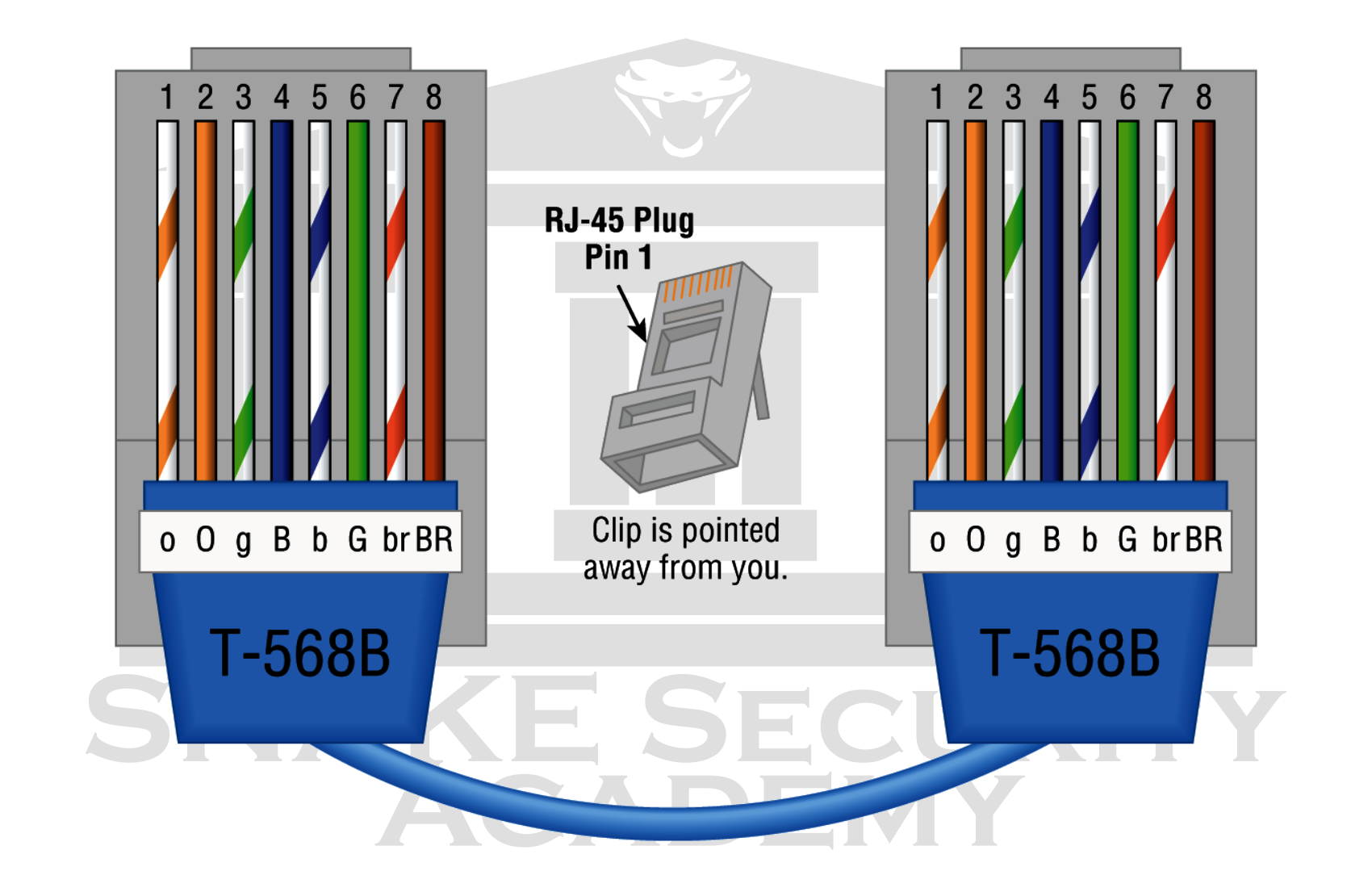
RJ-45 connector with T568B specification:

RJ-45 is primarily used in short-haul LANs (typically up to 100 meters). The RJ-48c wiring type would be used with a T1 connection, which is a long-haul wide area network (WAN). In addition, RJ-48c wiring is typically shielded to protect the signal. RJ-45 wiring is unshielded.
Fiber-Optic Cable
Fiber-optic cable doesn’t use electricity to transmit digital signals. Instead, it uses light pulses, making it immune to EMI and RFI.
Fiber-optic cable allows light pulses to be carried on either a core of glass or a core of plastic. Plastic costs less than glass, but glass can carry the signal farther. Regardless of the type of core, it’s surrounded by a cladding of either glass or plastic with a different index of refraction, which reflects the light back into the core. This is surrounded by a layer of flexible plastic buffer, which can be wrapped in armor, usually Kevlar, which is then wrapped in PVC or plenum.
The cable itself comes in either single-mode or multimode fiber; the difference between them is the number of light beams (the number of signals) they can carry. Multimode fiber is most commonly used for shorter distance applications and single mode fiber is used for longer distances.
Fiber-optic cable may sound like the solution to many problems. However, just like any other type of cable, it has its pros and cons.
Here are some of the advantages of fiber-optic cable:
- It’s completely immune to EMI and RFI.
- It can transmit up to 40 kilometers (about 25 miles).
And here are the disadvantages of using fiber-optic cable:
- It’s difficult to install.
- It’s more expensive than twisted-pair.
- The cost of troubleshooting equipment is higher than that of twisted-pair test equipment.
- It’s harder to troubleshoot.
Single-Mode Fiber
A Single-mode fiber-optic (SMF) cable is a very high-speed, long-distance medium that consists of a single strand - sometimes two strands - of glass fiber that carries the signals. The light sources used in SMF are light-emitting diodes (LEDs) and lasers. To create communication, the light source is transmitted and pulsed from end to end. Because it can transmit data up to 90 times farther than multimode fiber at a faster rate, this type of fiber is used to cover very long distances. Depending on the transceiver used, that’s 40 to 80 kilometers!
Multimode Fiber
Multimode fiber-optic (MMF) cable also uses light to transmit a signal, but in this case the light is scattered over a number of paths as it travels through the core and is reflected back. To line the core and focus the light back onto it, a special material called cladding is used. MMF provides a high bandwidth at high speeds over medium distances (up to about 3,000 feet), but it can be very inconsistent over longer distances. For this reason, MMF is most commonly used within a smaller area of a building. SMF can be used between buildings.
Fiber Connectors
In a fiber optic installation, there are several different fiber connectors that can be used. In a fiber optic installation, each fiber connector has an advantage or purpose. The visual differences between fiber connectors and their names are important to know.
Straight Tip
The Straight Tip (ST) connector was originally designed by AT&T for fiber optic cable. It is commonly used with the single mode fiber discussed earlier.

It is one of the most popular connectors used with fiber for WAN connectivity on SMF. The cable connector can be found in both SMF and MMF cable installations. The cable operates much like a BNC connector; it is a bayonet-style mechanism that you twist and lock into place. The advantage of this cable is that it will not come loose over time due to the positive locking mechanism.
Ferrule

The Ferrule Connector (FC) is a fiber-optic connector with a threaded body, which was designed for use in high-vibration environments. It is commonly used with both single-mode optical fiber and polarization-maintaining optical fiber. FC connectors are used in datacom, telecommunications, measurement equipment, and single-mode lasers. They are becoming less common, displaced by SC and LC connectors.
It looks the same as the ST connector, but it has a screw mechanism in place of the BNC connector.
Subscriber
The Subscriber Connector (SC) is a square connector with a floating ferrule that holds the fiber optic cable. The cable is supplied with a plastic clip that holds the transmit cable and the receive cable securely in place for insertion. In general, these clips allow the ends of the cable to be disassembled so that the transmit and receive cables can be interchanged.

It is found on both SMF and MMF systems, but is most commonly found on MMF systems.
The SC connector is starting to be replaced in new installations because it is larger than most modern connectors.
Small Form Factor
Another type of fiber-optic connector is the Small Form Factor (SFF) connector. This connector allows more fiber optic terminations in the same amount of space than its standard-sized counterparts.
The three most popular versions are AMP’s Mechanical Transfer Registered Jacks (MT-RJ/MTRJ), Lucent’s Local Connection (LC), and NTT Group’s developed and licensed Multifiber Push-On (MPO).
MT-RJ
The MT-RJ fiber-optic connector was the first small form factor fiber optic connector to be widely adopted, and it’s only one-third the size of the SC and ST connectors it most commonly replaces.

It offers these advantages:
- Small size
- TX and RX strands in one connector
- Keyed for single polarity
- Pre-terminated ends that require no polishing or epoxy
- Easy to use
LC
The Local Connector (LC) resembles an RJ-style connector; it has a spring-loaded latch similar to the RJ that holds it in place. The LC connector is a popular cable connector that is small enough to allow higher port densities on a switch. Commonly found on MMF and SMF optical cables. It is not possible to disassemble the cable as with the SC connector.

MPO
The Multifiber Push-On (MPO) Connector is another high density SFF fiber connector. It provides 2, 8, 12 or 24 fiber connections in a single connector.

APC vs UPC
Angled Physical Contact (APC) and Ultra Physical Contact (UPC) is not a connector; it is a termination on the connector end to curb optical decibel loss. Choosing between APC and UPC can make a big difference in your network performance.

The ultra-polished connector looks just like what you’d expect to find on the end of a fiber-optic cable. It has a perfectly straight cut.
The angle-polished Connector has a perfect angle cut to it. There’s an obvious reason why.
While the UPC connector reflects the light back to the fiber core causing a loss effect called “return loss”, the APC connector does not suffer from this problem because the angled cut reflects the light on the sides of the glass cladding instead of the core.
Fiber Distribution Panel
Fiber Distribution Panels (FDPs) are designed to terminate and distribute fiber-optic cable installations. The FDP consists of a cable management tray and a splice tray. Designed for central offices, remote offices, and LANs using fiber.
Fiber-Optic Transceivers
Fiber-optic transceivers can be either uni-directional (simplex) or bi-directional (duplex).
- uni-directional : A fiber-optic cable is uni-directional when it can only transmit data in one direction, either from the source to the destination or vice versa.
- bi-directional : A bi-directional fiber optic cable is capable of transmitting data in both directions at the same time.
By separating the transmission wavelengths of the two devices, communication over a single strand of fiber is achieved, as shown in the following figure.

Transceivers
A transceiver is a device that consists of both a transmitter and a receiver, which are combined together and share a common circuit or a single housing. This term refers to wireless communication devices such as cell phones, cordless phones, portable and mobile radio devices. It is sometimes used to refer to cable or fiber optic transmission and reception equipment.
SFP
The Small Form Factor Pluggable (SFP) is a compact pluggable optical module transceiver for telecom and data applications. The Enhanced Small Form Factor Pluggable (SFP+) transceiver is an enhanced version of the SFP that supports data rates up to 16 Gbps.
QSFP
The Quad Small Form Pluggable (QSFP) is another compact, hot-pluggable transceiver used in data communications applications. It provides an interface between a fiber optic cable or active or passive copper electrical connection and network hardware (such as servers and switches). It enables data rates ranging from 4x1 Gbps for QSFP and 4x10 Gbps for QSFP+ to the highest rate of 4x28 Gbps, known as QSFP28. This is used for 100 Gbps links.
Media Converters
Sometimes it’s necessary to change between different types of media. You may need to go from one type of fiber to another type of fiber, or in an even more extreme case, you may need to go from fiber to Ethernet. If you find yourself in this position, it’s important to understand some of the more common media conversion devices:
Single-Mode Fiber to Ethernet
These devices convert the signal from Ethernet and single-mode fiber by accepting one fiber connector and one Ethernet connector.
Multimode Fiber to Ethernet
These devices convert the signal from Ethernet and multimode fiber by accepting one fiber connector and one Ethernet connector.
Single-Mode to Multimode Fiber
These devices take one singlemode fiber connector and one multimode fiber connector and convert the signals between them.
Wiring Standards
Ethernet cabling, especially if you’re planning to work on a LAN, is an important thing to understand. There are several different types of cabling standards that are available:
- T568A
- T568B
- Straight-through
- Crossover
- Rolled/rollover
T568A vs. T568B
Look inside a network cable and you’ll find four pairs of wires twisted to prevent crosstalk; they’re also twisted to prevent EMI and eavesdropping. The same colors of pins must be used throughout a network for reception and transmission, but how do you decide which color wire goes to which pin? Good news, you don’t have to decide.
Although there is not 100% agreement, there are two cabling standards that have been agreed upon by more than 60 vendors, including AT&T, 3Com (acquired by HP), and Cisco. This means that over the years, some network jacks have used the T568A standard and some have used the T568B standard, which can cause a bit of confusion if you don’t know what you’re dealing with on your network.
If you look at the illustration below, you will see that the green pair is used for pins 1 and 2, but the orange pair is split to pins 3 and 6, separated by the blue pair. This is the specification: T568A

Now take a look at the T568B standard in the illustration below. The orange pairs are pins 1 and 2 and the green pairs are pins 3 and 6, separated by the blue pairs.
Remember, we are using the T568A standard and creating the kind of straight-through cable that is regularly implemented as a regular patch cable for most networks if we connect the green-white, green, orange-white, and orange wires to pins 1, 2, 3, and 6, respectively, on both sides of the cable. On the other hand, we’ve created a crossover cable for most networks by switching from pin 1 to pin 3 and pin 2 to pin 6 on one side only. Let’s see how that works out.
Straight-Through Cable
To connect a host to a switch or hub, or a router to a switch or hub, use the straight-through cable.
To connect 10/100 Ethernet devices, four wires are used in a straight-through cable. It’s actually quite easy to do this; the figure below shows the four wires that are used in a straight-through Ethernet cable.

Note that only pins 1, 2, 3 and 6 are used. Connect 1 to 1, 2 to 2, 3 to 3, and 6 to 6 and you’re up and networking in no time. Keep in mind that this is a 10/100 Ethernet-only cable, so it won’t work with 1000 Mbps or higher Ethernet.
Crossover Cable
This cable uses the same four wires, and just like the straight-through cable, you simply connect the different pins together. Crossover cables can be used to connect these devices:
- Switch to switch
- Hub to hub
- Host to host
- Hub to switch
- Router direct to host

OK, did you notice that we did not connect pins 1 with 1, 2 with 2, and so forth, but rather pins 1 with 3 and 2 with 6? Crossover cables are commonly used for connecting two switches, or for directly testing communication between two workstations.
Only Ethernet UTP installations use a crossover cable. You can use it to directly connect two workstation NICs or to directly connect a workstation and a server NIC.
This is what it would look like if you tried to match the straight-through and crossover cables to the T568A and T568B standards:
- T568A+T568A : straight-through
- T568B+T568B : straight-through
- T568A+T568B : crossover
UTP Gigabit Wiring (1000BaseT)
The previous examples of 10BaseT and 100BaseT UTP wiring used only two pairs of wires, but that’s not enough for Gigabit UTP transmission.
The 1000BaseT UTP wiring requires four pairs of wires and uses more advanced electronics so that each pair in the cable can transmit at the same time. However, except for using the other two pairs in the cable, Gigabit wiring is almost identical to the 10/100 example.
Crossover 1000BaseT UTP Cable:

NOTE:
It is still 1 to 1, 2 to 2, and so on up to pin 8 for make a straight-through Gigabit cable.